viflow logoknowledge base

Contact Us

Menu
en de
  • viflow product page
  • Support request

Contact Us

  • viflow knowledge base
  • viflow – help
  • Modeling in viflow
  • Modeling Process Graphics
  • Modeling Areas
Modeling Process Graphics

Modeling Areas

Applies to: viflow (subscription | 9 | 8) | Article: 1586262 | Updated on 30.04.2024

Various options are available for modeling areas in the process graphic.

Modeling new areas

  1. Open the process graphic that is to be modeled ( ››› Open process graphic).
  2. In the viflow stencil, left-click the Area or Area (OrgChart) shape, hold down the button, and drag the shape onto the drawing page.
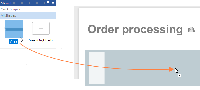
The Create Area window opens.
  3. Now enter the name of the area.Confirm the entry with OK.
  4. Double click on the area in the graphic to open the properties window.
    Alternatively, choose Properties from the context menu [  ] of the area.
    If necessary, enter a Short Name here and detail further global and local data of the area.
Delete

All information on detailing areas as well as on local and global properties can be found in the chapter ››› Properties of areas .

Delete

The Short Name of the area is displayed in the normal area shape (swimlane) in the text field on the left and (if set) in the watermarks.

The name appears at the top right of the swimlane shape.

Modeling existing areas

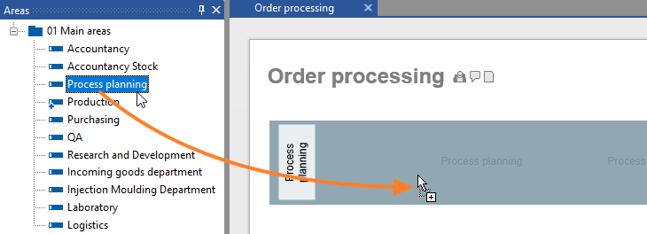
Areas that already exist in the process model can easily be used in process modeling by dragging them directly from the Areas window (or the Overview, Explorer windows) onto the drawing sheet.

Delete

When dragging the area onto the drawing page, the default area shape from the viflow stencil is used. If you want to use this function with a different area shape, first select the desired shape on the stencil and then drag the area from the window onto the drawing page.

Alternatively, proceed as described in point 1 under Modeling new areas. If you enter the first letters or parts of words, all areas containing them will be listed and offered for use.

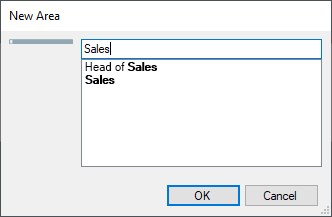
Click on the desired list entry and close the window with OK.

All articles in Modeling Process Graphics

  • Open process graphic
  • Modeling Areas
  • Modeling Processes and Decisions
  • Modeling Information Objects
  • Linking files and insert hyperlinks
  • Markers on the viflow Objects
  • Customizing Headers aund Footers of Graphics
  • Numbering of Processes
  • Change drawing sheet size
  • Connectors – Connections between Processes
Quicklinks
  • viflow international
  • viflow functions
  • Trainings
  • viflow life cycle
  • viflow system requirements
  • Remote support
  • viflow updates
SUBMIT SUPPORT REQUEST

Couldn't find a solution? Make a support request.

Submit a support request


FOLLOW US

We inform you regularly about current developments, trends and news around viflow. Just choose the format that's right for you.

Newsletter subscription
vilfow auf facebook ViCon auf Xing ViCon auf Linkedin vilfow auf youtube
Contact Central office

+49 511 696048-0

Sales

+49 511 696048-20

Support support@viflow.de
  • Contact
  • T&Cs
  • Conditions of Use
  • Privacy Statement
  • Legal Info

Copyright © 2003 – 2025 ViCon GmbH | viflow knowledge base | All rights reserved.

info@vicon.biz +49 511 696048-0
Knowledge Base Software powered by Helpjuice

Definition by Author

0
0
  • Kontakt
  • AGB
  • Nutzungsbedingungen
  • Datenschutz
  • Impressum

Copyright © 2003 – 2021 ViCon GmbH | Funktionen | Alle Rechte vorbehalten.

info@vicon.biz +49 511 696048-0
Expand