
Connectors – Connections between Processes
Applies to: viflow (subscription | 9 | 8) | Article: 1586442 | Updated on 30.04.2024
If the requirements for connecting processes with connectors are met, the connection can be activated or removed with the Connectors button. In order for a connector ("information arrows" in the graphic) to be used as a connector, the following conditions must be met:
- The connector ("information arrow") is used in at least two graphics and is connected to a process shape in each case.
- A process shape "gives up the connector", there is no successor process.
- A process shape "picks up the connector", there is no process as a predecessor.
After clicking the Connectors button, all active and inactive connections are displayed. Clicking on an inactive connector connection activates it and clicking on an active connection removes it.
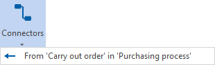 |
Inactive connector – clicking activates the function. |
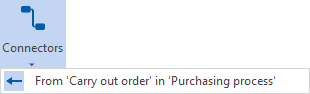 |
Active connector – clicking disables the feature. |
Different processes can be connected with each other with the help of connectors. Connectors are pieces of information (information arrows in the graphic) that are only connected to a process symbol on one side. The beginning of the arrow or the tip of the arrow point into the void and indicate a connection that leads to or from a process.
In the WebModel, the connectors are provided with references to the associated processes:
The big advantage for the user is that you can jump to another process graphic in the WebModel with one click, without first navigating in the process model or searching for the target process in the search window.
For connectors to work correctly, they must be used in at least two processes and defined as a connector:
- Usage in the process that "dispenses" the connector
- Usage in the process that "picks up" the connector
- In addition, the connector must be activated in the Insert tab with the Connectors button
The principle of the connectors is shown schematically in the following graphics.
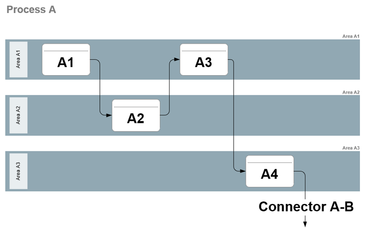
The connector comes from "Process A", sub-process "A4" with the goal...
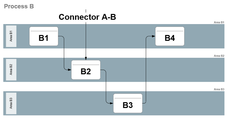
... "Process B", sub-process "B2".
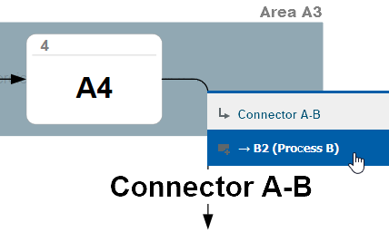
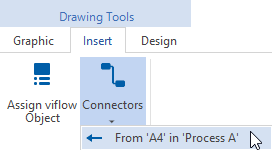
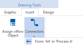
Now the information in the Inserttab only has to be defined as a connector. To do this, click on the connection to be established, here: "to B2 in process B".
You can then recognize the now activated connector by the marked arrow  .
.
Creating and activating a Connector
- Open or model the process graphic that the connector should later "leave" (here process "A").
- Create a connector that starts at the desired process (here process "A4") and has no descendant.
You can also use existing information and drag it from the process model onto the drawing sheet (in this case, step "4" is omitted). - Right-click the connection arrow and select Properties from the context menu.
The properties window will open. - Enter the name of the information (here as an example "Connector AB") and save the process graphic.
- Open or model the target process graphic (here process "B").
- Now use the information created above and model it without a process predecessor (!) as an input into a sub-process of the target process (here process "B2").
To do this, drag the information from the Information window directly onto the drawing sheet or open the properties of a new connector and select the information used above in the Name field (after entering the first few letters).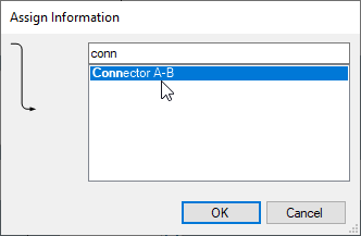 Save the process graphic.
 - Select the connector in the graphic and click on the Connectors button in the Insert tab.
The possible connections to other processes are displayed. - Click on the desired connection to another process (here: To 'B2' in 'Process B').
The information is now defined as a connector.
If you click the Connectors button again, the connection is indicated by the highlighted arrow.png) recognized as active.
recognized as active.
Disable a Connector
- Highlight the connector you want to disable in a graphic.
- On the Insert tab, click the Connectors button.
The active connections to other processes are displayed [.png) ].
]. - Click on the connection to be deleted, the following window appears:
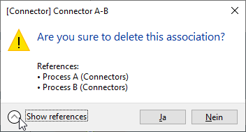 Under Show references you can see the use of the connector for checking purposes.
Confirm the message with Yes .
The connection to the other process is removed and displayed as deactivated after clicking the Connectors button again.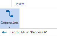
.png) ] on an entry and choose the Delete command.
] on an entry and choose the Delete command.